Hardware architecture
Introduction
Ledger signers use a distinctive architecture that combines the security of the Secure Element with support for several peripherals. These peripherals include the screen, buttons, a host computer connected over USB, and, for the Ledger Blue, Bluetooth and NFC.
The architecture connects an additional STM32 microcontroller (MCU) to the Secure Element (SE). The MCU acts as a simple router between the SE and the peripherals. It does not perform application logic or store any cryptographic secrets used by Ledger OS. Instead, it manages the peripherals and notifies the SE when new data is ready. Ledger OS runs applications entirely on the SE. This section describes the hardware architecture and its constraints before examining their software implications.
Multiple processors: Secure Element proxy
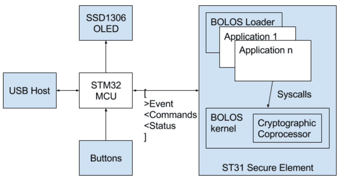 A detailed Ledger OS architecture diagram
Ledger OS uses two hardware chips. One is secure; the other has JTAG enabled and acts as a proxy.
| Hardware signer | Microcontroller (MCU) | Secure Element (SE) |
|---|---|---|
| Ledger Nano X | STM32WB55 / STM32WB35 | ST33J2M0 |
| Ledger Nano S Plus | STM32F042 | ST33K1M5C |
| Ledger Stax | STM32WB35 | ST33K1M5C |
| Ledger Flex | STM32WB35 | ST33K1M5C |
The Secure Element also contains two parts: firmware that is under NDA and therefore closed source, and SDK and application-loaded code that is open-source friendly. The Ledger OS firmware handles low-level I/O operations and implements the SE-MCU link. The running app handles the protocol between the SE and the MCU.
Ledger OS relies on both chips to support Secure Element applications. The SE is powerful but lacks inputs and outputs. The MCU provides them and acts as the SE’s proxy. In this sense, the MCU serves as a coprocessor for the SE. Through a simple asynchronous protocol, the SE controls the proxy. The security implications of this design are outside the scope of this section.
The SE-MCU link protocol is called SEPROXYHAL, or SEPH, in source code and documentation. “HAL” stands for Hardware Abstraction Layer.
SEPROXYHAL
The SEPROXYHAL protocol uses a serialized list of three packet types: Events, Commands, and Statuses. It is the SE’s only channel for communicating with the outside world. A protocol error, such as an incorrect packet order or format, isolates the SE and prevents communication. This is typically the most common failure scenario during application development. If it occurs, you must reboot the signer to reset the SEPROXYHAL protocol state. Software guards are intended to help prevent these errors.
The protocol begins when the MCU sends an Event, such as a button press, ticker, or USB transfer. The SE responds to the Event with zero or more Commands. It then sends a Status to indicate that it has fully processed the Event and waits for the next one.
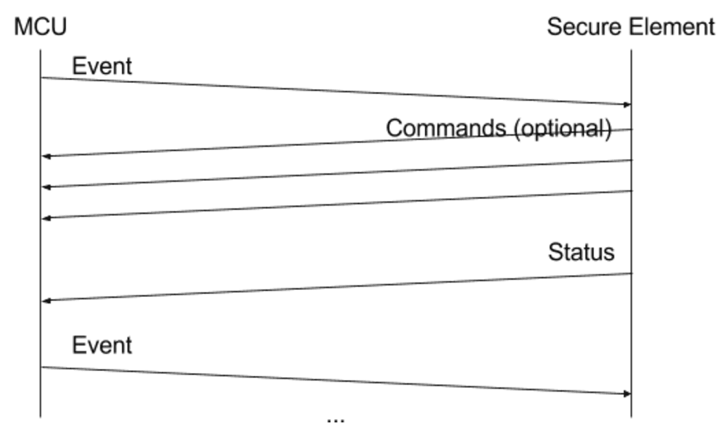 SEPROXYHAL protocol concept
Because of the buffer size, the SE uses a Status to send requests to display content on the screen. After processing the Display Status, the MCU issues a Display Processed Event to indicate that it is ready for another Display Status. Building a complete user interface requires the application to display multiple elements asynchronously from its core logic. A UX helper in the SDK supports this process, as discussed in the next chapter.
The SE throws an exception if an application sends more than one Status in a row without fetching a new Event between them.
